In digital copying and printing imaging systems, the carrier—an often overlooked yet indispensable core consumable component—is officially called the photocopier carrier, commonly known as iron powder.
It doesn’t directly participate in paper imaging and isn’t printed out, but it serves as the core medium connecting toner and the OPC drum. It directly determines the clarity, color uniformity, and density stability of the printed image, while also affecting the operating efficiency and lifespan of office equipment.
As a core component of the two-component development system, the technological iteration of the carrier has spanned the entire development process of copiers, from analog to digital, from black and white to color, and from low speed to high speed. This article will systematically review the development process of copier carriers, their core working principles, and their key role in printing imaging, while analyzing their future development direction in conjunction with industry trends.
I. The Development History of Copier Carriers
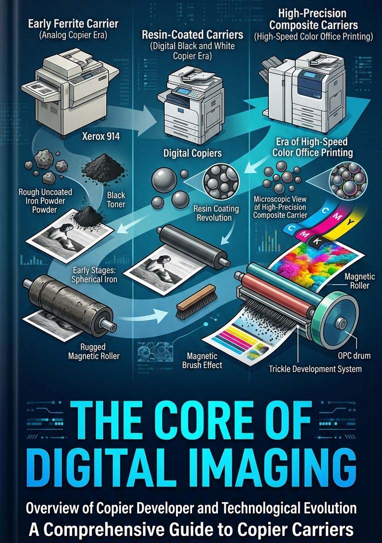
The development of copier carriers has always closely followed the iterative upgrades of electrostatic copying technology, gradually iterating from simple materials to high-precision, high-stability composite functional materials. Overall, it can be divided into three core development stages. Each technological innovation solved the imaging defects and equipment compatibility issues of the previous generation, maximizing print quality and print volume, and perfectly matching machines with faster printing speeds.

(1) Early Ferrite First-Generation Uncoated Ferrite Carrier (Analog Copier Era)
Early Stages: Natural Sand and Spherical Iron (1950s-1970s)
In the earliest commercial electrostatic copiers (the groundbreaking Xerox 914 being a prime example), the development system required a uniform spherical carrier. The earliest carrier particles were actually specially made fine-grained natural sand or tiny glass beads, these were completely uncoated, relying entirely on the natural surface properties of glass or silica to generate triboelectric charging to charge the early thermoplastic toners.
Spherical Iron Powder: As machines transitioned from Gravity-Assisted Electrostatic Development to Magnetic Brush Development, the carrier had to be magnetic. Manufacturers began using atomized iron or reduced iron powder. However, this carrier had significant limitations.
High density: Iron is heavy (7.8 g/cm³). This required enormous mechanical torque to agitate the developer, leading to high energy consumption and rapid wear of development components. Because the iron beads were uncoated, friction and heat caused the toner particles to melt and clump together. Once covered in toner, the carrier loses its ability to recharge with new toner, leading to a rapid decline in copy quality and the need for frequent developer replacements.
(2) Resin-Coated Carriers (Digital Black and White Copier Era)
The Polymer Coating Revolution (Late 1970s to 1980s)
To solve the serious problem of toner melting and clumping, manufacturers began coating the iron core with an ultra-thin polymer layer.
Materials used: Early coatings used fluoropolymers (such as PTFE or PVDF) to provide negative charge characteristics, or acrylic/styrene copolymers to provide positive charging characteristics, depending on the requirements of the Organic Photoconductor (OPC) or drum unit. The polymer coating acted as a physical barrier, solving the problem of frictional overheating and preventing the toner from melting directly. Engineers also fine-tuned the charging capability of the carrier coating by changing its chemical composition.
(3) Core Material Upgrade
The Shift to Ferrite Cores (1980s to 1990s)
As copier speeds increased and consumers demanded higher quality halftone reproduction, iron core performance reached its limits. The industry began a major shift towards ferrite materials. What are ferrites? Ferrites are ceramic compounds composed of transition metals and iron oxide (e.g., copper-zinc ferrite, manganese-magnesium ferrite, or nickel-zinc ferrite).
Advantages compared to iron:
Lower density: Ferrites have a much lower density than pure iron (approximately 4.5 to 5.0 g/cm³). This significantly reduces the torque required to agitate the developer, minimizes heat generation, and extends the lifespan of development components and the developer itself.
Higher resistivity: Ferrite cores allow for better control of the development electric field, reducing background scattering and resulting in clearer text and lines.
Optimized particle size: With the introduction of ferrites, the average particle size is reduced from over 100 micrometers to 60 to 80 micrometers.
(4) High-precision composite carriers (the era of high-speed color office printing)
With the explosive growth of high-speed digital color copiers and production printers, traditional ferrite carriers face new challenges. Color printing requires extremely precise toner concentration (TC) control and absolute stability over hundreds of thousands of prints.
Manufacturers have developed Binder Carriers: Magnetic Resin Carriers (MRC) / Binder-type Carriers, instead of traditional solid ceramic or metal cores. These carriers consist of micronized magnetic powders (such as magnetite nanoparticles) uniformly dispersed in a tough polymer resin matrix.
Ultra-low density: Their density can be as low as 3.0 to 3.5 g/cm³.
Smaller size: This technology allows carrier particle sizes to be safely reduced to 30 to 50μm while effectively preventing carrier adhesion onto the OPC drum. Some high-end carriers also incorporate wear-resistant, anti-static, and moisture-resistant modified components, providing greater environmental stability and making them suitable for complex office environments such as high temperature and high humidity, effectively reducing carrier wear during high-speed printing. Modern breakthroughs lie not only in the carrier itself but also in the way carriers are managed within the copier.
In high-speed color copiers, a small amount of fresh carrier is pre-mixed into the toner bottle. As toner is consumed, fresh carrier is continuously fed into the development unit, while a corresponding amount of degraded, fatigued carrier overflows into the waste toner cartridge. This “Trickle Development System” stabilizes triboelectric charge characteristics during the printing of millions of pages, effectively avoiding the tedious operation that previously required technicians to frequently change the developer.
II. Core Working Principle of the Copier Developer
The copier developer works synergistically based on the principles of magnetic adsorption and triboelectric charging. It is the core power medium of the two-component development system (carrier + toner). The entire working process is cyclical and low-loss, which is the core characteristic that distinguishes the carrier from toner—toner is a consumable, while the carrier can be reused for a long time, only slowly aging and failing due to long-term mechanical wear.
The core working principle of the carrier revolves around two basic concepts: triboelectric charging (static electricity generated by friction) and magnetism.
In a two-component developing system: the carrier and toner work together like a “truck and cargo.” The carrier is the reusable truck, while the toner is the cargo actually delivered to the paper.
The detailed steps of the carrier’s operation in the development unit are as follows:
1. Triboelectric Charging (Electrostatic “Adhesive”)
Before printing, the toner and the carrier are vigorously mixed in the copier’s development unit by a high-speed rotating screw conveyor.
Frictional Contact: When the carrier beads rub against the toner particles, the triboelectric effect generates static electrical charges.
Charge Transfer: Depending on the materials used for the carrier coating and the toner resin, electrons are transferred between them. For example, in a negative-toner development system, the carrier transfers electrons to the toner.
The Result: The toner becomes negatively charged, and the carrier becomes positively charged (and vice versa). Due to the attraction between opposite charges, the tiny toner particles adhere tightly to the larger carrier surface, completely covering it.
2. Transport to OPC drum
Once the carrier beads are encapsulated with toner, the magnetic roller adsorbs the developer mixture onto its sleeve surface.
Meanwhile, following laser exposure on the OPC drum, an invisible electrostatic latent image is formed on its photoconductive surface. As the magnetic roller approaches the drum:
Selective Development: Driven by the development electric field, the charged toner particles overcome their electrostatic bond with the carrier and are selectively attracted from the carrier surface onto the exposed latent image areas of the OPC drum.
Magnetic Roller Structure: The magnetic roller consists of a rotating aluminum sleeve surrounding a stationary internal permanent magnet core.
Magnetic Alignment: Because the carrier cores are made of magnetic materials (such as ferrite or iron oxide), the carrier beads align themselves along the magnetic flux lines radiating from the roller.
Magnetic Brush Effect: This alignment causes the carrier beads to chain together, standing vertically like the bristles of a brush. Known in the industry as the “magnetic brush,” this structure gently sweeps across the OPC drum surface, enabling high-precision toner transfer.
3. Development Zone (Hand-off)
As the magnetic roller rotates, the “bristles” (carrier beads covered with toner) gently rub or approach the rotating OPC drum at an ultra-close distance.
Electrostatic Confrontation: A latent image formed by laser or LED is stored on the OPC drum, and the voltage of the exposed area is lower than that of the unexposed area.
Overcoming Electrostatic Adsorption: In the development gap, an development bias (a mixture of AC and DC) is applied to the magnetic roller. This bias generates a powerful electric field that attracts the charged toner.
Hand-off: The electrostatic attraction between the laser-exposed area on the photosensitive drum and the toner is stronger than the triboelectric adsorption force between the toner and the carrier. Toner particles detach from the carrier beads and leap onto the OPC drum for development.
Carrier Beads Adsorption: Because the carrier beads are magnetic, they are firmly adsorbed by the magnet inside the development roller and will not leap onto the OPC drum.
4. Return to Circulation (Reloading)
After passing through the development zone, these “hungry” carriers (now unloaded of toner) are carried away by the rotating magnetic roller.
Peeling and Mixing: As the magnetic roller rotates through the magnetic field free zone, the carrier beads detach from the roller and fall back into the mixing tank.
Circulation: In the mixing tank, the lightly loaded carriers mix with fresh toner from the toner cartridge, restarting the triboelectric charging process.
The carriers’ sole purpose is to charge the toner, enabling it to be controlled by the electric field and physically transported to the OPC drum via magnetic force, before being released and returned for the next toner loading.
III. The Core Role of the Carrier in Printing Imaging
As a core control component of the developing system, the carrier, while not directly involved in imaging, comprehensively determines print quality and equipment operation. Its core role is concentrated in three dimensions: image quality, equipment stability, and cost control.
(1) Precise Electrical Control, Ensuring Image Clarity and Stability
This is the carrier’s most crucial function. A high-quality carrier provides a stable and uniform triboelectric charge to the toner, allowing it to be precisely adsorbed onto the latent image area of the OPC drum. This avoids problems such as faint print, missing colors, and low resolution caused by insufficient toner adsorption, and also prevents issues like background fogging, ghosting, toner scattering, and image smudges caused by toner charge distribution broadness.
In color printing, a high-precision carrier can accurately match the charge-to-mass ratio (Q/m) parameters of the four-color toners, ensuring accurate color reproduction and natural tonal transitions, avoiding color deviation and insufficient saturation, and significantly improving color imaging quality.
(2) Uniform Toner Delivery, Maintaining Dynamic Balance of the Development System
The carrier, through magnetic adsorption, evenly disperses toner on the surface of the development magnetic roller, forming a uniform development layer. This ensures consistent toner adhesion density across the entire image, preventing uneven color depth and patchy areas. Simultaneously, the carrier can regulate the toner concentration (TC) in the developer unit in real time. When toner is consumed, the carrier quickly mixes and becomes charged with newly added toner, rapidly restoring the development balance and ensuring consistently stable and uniform image quality without significant fluctuations during continuous high-speed printing.
(3) Protecting Equipment, Reducing Failure and Maintenance Costs
Qualified carrier particles are round, uniform, and highly wear-resistant, free of dust and debris. This effectively reduces wear on the developer unit, magnetic roller, and OPC drum, preventing rough particles from scratching delicate components. Furthermore, a stable carrier significantly reduces toner scattering and leakage, lowering the probability of internal equipment contamination, reducing paper jams, imaging malfunctions, and equipment errors, and extending the lifespan of the development assembly and OPC drum. Conversely, aging, failure, or poor quality of the carrier can directly trigger a series of equipment malfunctions, increasing maintenance frequency and consumable costs, and significantly raising office operation and maintenance costs.
(4) Adapting to High-Speed Printing and Improving Office Efficiency
Modern high-speed digital multifunction printers can print at speeds exceeding 100 pages per minute, requiring extremely fast development response times. High-precision carriers have fast charge response speeds and strong magnetic stability, allowing them to adapt to the rhythm of high-speed equipment operation. During rapid cyclical operation, they maintain stable toner delivery and charging performance, preventing problems such as toner charge distribution broadness and uneven toner delivery due to high-speed operation. This ensures high-speed, continuous, and stable operation of the equipment, meeting the needs of batch office printing.
IV. Future Development Prospects of the Copier Carrier Industry
With the development of intelligent, green, and high-precision office environments, digital copier equipment is constantly iterating and upgrading. High-definition imaging, high-speed printing, energy saving and environmental protection, and low maintenance costs have become core trends in the industry, driving copier carriers to continuously upgrade towards refinement, long-lasting performance, greenness, and intelligence. Future carrier technology will exhibit four major development trends:
Trend1: Future carriers will further develop towards miniaturization and uniformity, with particle size distribution (PSD) precisely controlled within the 20-40μm range.
Trend2: through nano-coating modification technology, the carrier’s triboelectric charging properties will be more precise and stable, making it compatible with ultra-high-definition printing equipment of 1200dpi and above, perfectly presenting fine text, complex patterns, and gradient colors, completely solving the problems of detail loss and color distortion in high-definition imaging.
Trend3: Future carrier coatings will use new composite coating materials with high wear resistance, high oxidation resistance, and anti-aging properties. Through multi-layer composite modification processes, the coating adhesion, wear resistance, and environmental stability of the carrier coating will be improved, significantly extending the carrier’s service life.
Trend4: In the future, the carrier will fully utilize recyclable and environmentally friendly resin coating materials, optimize production processes, reduce pollutant emissions during production, achieve resource recycling, and align with the industry development trend of energy conservation, environmental protection, and green office practices.
V. Common Abnormalities and Solutions for Copier Carriers
As the core development medium in a cyclical process, the carrier is susceptible to abnormalities due to prolonged high-speed operation, environmental interference, improper consumable compatibility, and untimely maintenance. These abnormalities directly lead to print/copy quality defects, equipment errors, and component wear. Based on the working principles of the carrier and practical experience in office equipment maintenance, this section systematically summarizes common carrier abnormalities, their causes, and standardized solutions, covering three main scenarios: image quality failures, equipment operation failures, and consumable compatibility failures.
(1) Severe Background Fogging and Overall Darkness in Printed Images
Fault Phenomenon: The printed/copied paper has a gray background, covered with a uniform light gray, with no pure white effect in blank areas, and blurred text edges. The background fogging becomes more pronounced after batch printing.
Core causes:
1. Carrier aging and fatigue: After long-term use, the surface resin coating wears down, reducing its triboelectric charging ability and preventing complete toner adsorption, resulting in a large amount of toner scattering.
2. Imbalance between toner and carrier in the developer unit: Excessive toner and insufficient carrier exceed the carrier’s adsorption capacity.
3. Humid environment: Moisture reduces the resistivity of the carrier and toner, disrupting their charging properties.
4. Uneven mixing in the developer unit: Toner agglomeration, causing uncontrolled image density (ID).
Solution:
Remove the carrier and toner and place them in a dry, ventilated environment to dry them.
Reinstall the developer assembly, calibrate the toner concentration (TC calibration), and restore the standard carrier-to-toner ratio.
Note: Excess toner can be consumed by printing a solid black page or by forced toner supply.
(2) Faint print, missing colors, uneven density
Fault symptoms: Faint and blurry text lines; insufficient saturation and localized color loss in color printing blocks; uneven image density across the entire image; image quality continuously deteriorates after high-speed continuous printing.
Core Causes:
1. Long-term use leads to magnetic attenuation and unstable charge output on the carrier, resulting in insufficient toner adsorption and transport capacity;
2. Carrier particle wear and pulverization, excessive dust, and uneven magnetic brush formation;
3. Substandard toner quality, mismatch with carrier charge-to-mass ratio (Q/m) parameters, and poor triboelectric charging effect;
4. Insufficient carrier volume in the developer unit, preventing the formation of a complete and uniform magnetic brush layer.
Solutions:
Clean carrier dust and waste toner impurities from the developer unit;
Replace with an original, compatible carrier or a high-quality compatible carrier;
Perform toner concentration calibration (TC calibration) and development parameter initialization procedures upon startup to stabilize carrier charge and toner transport performance;
For color equipment, separately calibrate the carrier status of the four-color developer units to repair issues such as pale or missing colors.
(3) Carrier and Toner Scattering/Leakage, Severe Internal Equipment Contamination
Fault Phenomenon: Scattered brown iron powder particles appear inside the equipment, at paper edges, and at the paper exit; severe toner accumulation inside the machine body; long-term scattering flying will contaminate the OPC drum and fusing assembly.
Core Causes:
1. Carrier aging and breakage, particle pulverization, fine dust cannot be stably adsorbed by the magnetic roller, resulting in scattering;
2. Aging and damage to the sealing strips of the developer unit, and improper closure of the cover, leading to carrier leakage;
3. Poor toner quality or incompatible performance.
Solutions:
Check and replace aging developer unit sealing strips, sponges, clips, and other accessories to ensure a tight seal;
Replace with new, high-quality, uniform carrier or toner.
(4) Black Lines, Black Dots, and Particulate Impurities on Printed Images
Symptoms: Fixed black lines, irregular black dots, and hard particle protrusions appear in the paper transport direction; some black dots can be wiped off, while others are fused onto the paper surface.
Core Causes:
1. Carrier clumping and the presence of hard impurities, which scratch the OPC drum as the magnetic brush rotates, forming regular black lines.
2. Damaged carrier particles adhere to the OPC drum and cleaning blade surface, continuously contaminating the imaging interface.
3. Impurities accumulate in the developer unit, resulting in poor mixing of carrier and toner, leading to particulate impurities during imaging.
Solution:
Disassemble the developer assembly, thoroughly clean the clumped carrier and internal impurities, and wipe the surfaces of the magnetic roller, OPC drum, and cleaning blade clean;
Replace with a new carrier, remix the toner, and avoid residual impurities;
After installation, print ten blank pages to remove residual impurities before formal printing.
(5) Developer Unit Jamming, High Operating Resistance, and Equipment Errors
Symptoms: Abnormal noises during equipment operation, jamming of the developer assembly, frequent development fault codes (service codes), and in severe cases, inability to start printing.
Core Causes:
1. Overfilling of the carrier, excessive load on the developer unit, obstructing agitation and magnetic roller operation.
2. Toner buildup clogging the developer unit, increasing operating resistance.
3. Carrier becoming damp, hardening, and clumping, increasing internal frictional resistance.
4. Wear of the development gears and clutch, causing jamming and malfunction.
Solution:
If this occurs immediately after installation, please remove the developer assembly (or the integrated drum/developer unit), shake it horizontally left and right, then manually rotate the drive gear.
If it rotates easily, it can be smoothly reinserted into the copier. (Side transport can cause the carrier to accumulate on one side).
If there is excess or clumping, remove the developer unit, clean off excess carrier and accumulated toner, retaining only the standard amount of carrier;
Break up the clumps of carrier and clean internal blockages; inspect and lubricate the development drive gears and clutch, and replace worn or aged transmission parts;
Manually rotate the unit after installation to test smooth operation before powering on for calibration.
(6) Premature Carrier Aging and Significantly Shortened Service Life
Fault Phenomenon: Before the replacement cycle, the carrier exhibits problems such as electrical failure, toner scattering, and poor imaging, and fails again shortly after replacement.
Core Causes:
1. Use of incompatible generic toner; mismatched chemical property parameters and electrical conductivity with the carrier accelerate carrier coating wear.
2. Prolonged operation of the equipment in a high-temperature, high-humidity, and dusty environment accelerates carrier coating oxidation and aging.
3. Frequent start-ups and shutdowns, and no-load operation lead to ineffective frictional wear of the carrier.
4. Developer unit malfunction causes long-term abnormal wear of the carrier.
Solutions:
Use original or compatible toner for the entire process, avoiding the mixing of inferior consumables;
Optimize the equipment operating environment, keeping it dry, ventilated, and dust-free;
Reduce ineffective idle operation of the equipment, and standardize start-up and shutdown procedures;
Regularly inspect the development components, magnetic rollers, and stirring structure to eliminate abnormal mechanical wear;
Regularly check the carrier, promptly removing pulverized or aged carrier particles.
(7) Color Printing Color Deviation and Layer Distortion
Fault Symptoms: Color text and images show color deviation, low saturation, harsh color transitions, unbalanced four-color imaging, and poor image layering.
Core Causes:
1. Imbalance in the four-color parameters of the color carrier; aging or abnormal charging of one color carrier.
2. Insufficient matching between the carrier and color toner, resulting in uneven adsorption of each color toner.
3. Lack of regular color calibration, leading to carrier development parameter deviation.
Solutions:
Check the carrier status of the four-color developer units separately, replacing aged or ineffective single-color carriers;
Use matching color toner of the same brand and series to ensure consistent consumable parameters;
After replacing the carrier, perform equipment color calibration and development parameter initialization to correct color deviation issues.
VI. How to Choose the Right Developer
Brand-new original carrier (OEM) > High-quality compatible new carrier > Model-specific reprocessed original carrier (Remanufactured OEM)
Note: Original carriers are designed for specific models; even if dimensions appear similar, minute differences in surface coating charge-to-mass ratio (Q/m) can lead to poor print quality. Our company utilizes proprietary reprocessing equipment to perform model-specific screening and processing, achieving carrier quality that rivals the original.
VII. Conclusion
The century-long evolution of copier carriers—from early, simple iron powders to high-precision, eco-friendly composite carriers—mirrors the continuous advancement of electrostatic imaging technology and the ongoing optimization of office equipment. As the core medium in two-component development systems, the carrier may seem inconspicuous, yet it dictates image density, operational stability, and maintenance costs. Looking ahead, as technologies for high-definition imaging, low-carbon sustainability, and smart offices mature, copier carriers will continue to overcome material and process limitations. They will evolve to become more refined, durable, eco-friendly, and intelligent, providing robust technical support for modern office printing environments characterized by high efficiency, superior quality, and sustainability.