Toner, Drum Unit, and Fuser Compatibility: An Engineering Guide to Print Quality and Reliability
How toner formulation, electrophotographic development, photoconductor cleaning, and fusing conditions interact—and why compatible consumables must be validated as a system.
introduction: Compatibility Is a System-Level Issue
In the copier and multifunction-printer (MFP) industry, toner, drum units, and fuser assemblies are often purchased, tested, and discussed as separate products. In operation, however, they are interdependent parts of one electrophotographic imaging process. Their interaction has a direct effect on image quality, consumable life, machine cleanliness, and operating cost.
Toner is not simply a black or colored powder. It is an engineered material designed to acquire and retain an appropriate electrostatic charge, move through the development system, transfer efficiently, clean reliably from the photoconductor when necessary, and fuse to the paper without sticking to the fuser surface. The drum or photoconductor unit provides the imaging surface and, depending on the machine architecture, may incorporate charging, cleaning, waste-toner collection, or other functions. The fuser then applies heat and pressure so the toner image becomes durable.
A toner that performs well in one engine may not perform equally well in another. Likewise, an OPC drum, cleaning blade, developer, or fuser component that meets its own dimensional or material specifications does not automatically guarantee a stable result when combined with a different toner formulation. Mismatches can contribute to background fog, low image density, uneven development, residual toner, ghosting, poor fixation, hot offset, or accelerated component wear. These symptoms are not unique to compatibility problems, so they must be diagnosed systematically.
The central engineering principle is straightforward: compatible consumables should be evaluated not only as individual parts, but also as a combination operating in the intended machine under defined conditions.
1. How Toner Technology Has Evolved
1.1 From xerography to modern toner
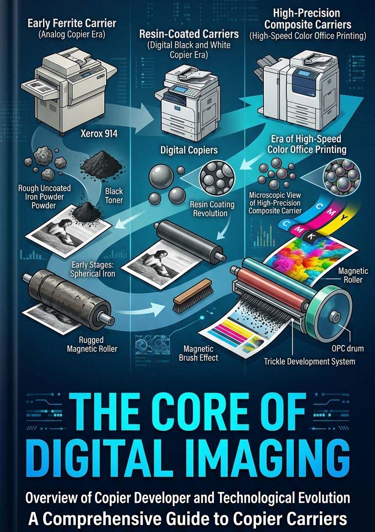
Chester Carlson demonstrated xerography in 1938. The launch of the Xerox 914 in 1959 helped bring automatic plain-paper xerographic copying into offices. The underlying principle remains central to many modern copiers and laser printers: an electrostatic latent image is formed on a photoconductor, charged toner develops that image, the image is transferred to a substrate, and heat and pressure fix it to the paper. [1]
As machines have become faster and more capable, toner development has had to balance a wider range of requirements, including fine detail, low-temperature fusing, stable charging, high transfer efficiency, low background, reliable cleaning, and consistent performance across different papers and environments.
1.2 Mechanically pulverized toner
Conventional pulverized toner is generally made by blending resin, colorant, charge-control materials, wax or another release agent, and other formulation ingredients; melt-kneading the blend; cooling it; and then grinding and classifying the material to obtain the required particle distribution. The resulting particles are commonly irregular rather than perfectly spherical. Actual particle size and shape vary with the formulation and manufacturing process, so a single size range should not be treated as universal.
Pulverized toner is based on a mature manufacturing route and can be formulated for many established print-engine designs. Its performance depends on more than particle shape: resin chemistry, particle-size distribution, surface additives, charge behavior, flow, and the interaction with the target developer and cleaning system all matter.
1.3 Chemically prepared toner
Chemically prepared toners include emulsion-aggregation (EA) toner and other polymerization-based processes. EA generally builds toner particles by aggregating smaller resin and pigment-containing components, followed by controlled coalescence. These processes can provide close control over particle size, size distribution, and shape. Shape-optimized particles and carefully designed resin/wax structures can support high-resolution imaging and lower-energy fusing, depending on the formulation and application. [2]
Chemical preparation does not automatically make a toner superior in every respect, and spherical particles are not a guarantee of compatibility. A toner must still be designed around the charging, development, transfer, cleaning, and fusing requirements of the target machine.
1.4 What is toner made of?
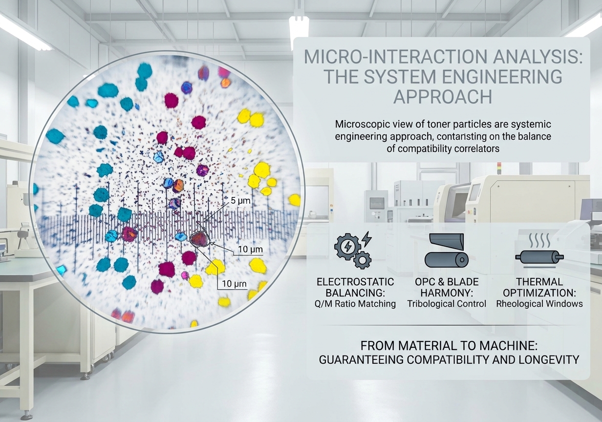
Dry toner is a functional composite, typically containing a polymer binder, colorant, charge-control ingredients, release agents, and surface additives. The exact chemistry differs by product and print engine.
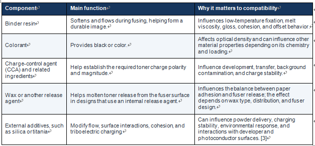
Small formulation changes can alter how toner particles interact with one another and with surrounding surfaces. Two toners that look similar and have similar average particle sizes may still differ in charge distribution, flow, transfer behavior, or fusing performance.
2. The Electrophotographic Imaging Cycle
Understanding compatibility begins with the full imaging process. The exact sequence and hardware differ among machines, but a typical dry-toner process contains the following stages:
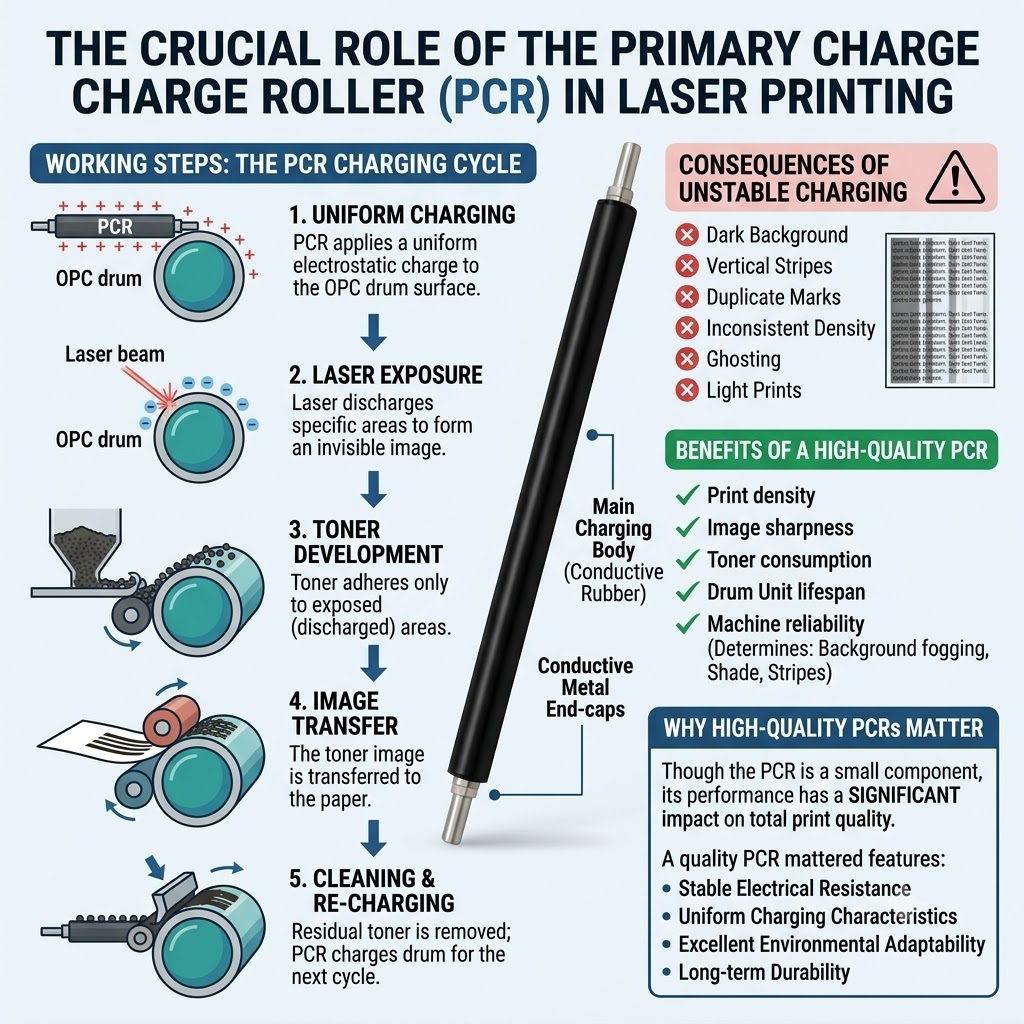
1. Charging: A charging roller or another charging device establishes the required electrical condition on the photoconductor surface.
2. Exposure: A laser or LED selectively changes the photoconductor’s surface potential, forming an electrostatic latent image.
3. Development: Charged toner is delivered to the photoconductor and attracted to the image areas according to the engine’s electrostatic design.
4. Transfer: An electric field transfers the developed toner image to paper or, in many color machines, first to an intermediate transfer belt.
5. Fusing: Heat and pressure cause toner particles to coalesce and adhere to the paper surface.
6. Cleaning and reset: Residual toner is removed from the photoconductor where required, and the imaging surface is prepared for the next cycle.
These are connected stages, but not every machine places all functions in the same replaceable assembly. Some designs use a separate photoconductor unit and developer unit; others integrate more functions into a cartridge or process unit. Compatibility analysis should therefore be based on the actual architecture of the target model, rather than on the generic name of a consumable.
3. Why Toner and the Drum/Development System Must Be Matched
3.1 Toner charge: the average Q/M is not the whole story
The charge-to-mass ratio (Q/M, commonly reported in microcoulombs per gram) describes the net electrical charge carried per unit mass of toner. In many electrophotographic systems, toner charge affects how much toner develops, how sharply image edges are reproduced, and how much toner is left in non-image areas. Both the magnitude and the sign of the charge matter. The distribution of charge among individual particles matters too: a satisfactory average can conceal a population of low-charge or wrong-sign particles that degrades image quality. [4]
There is no universal Q/M target for all copiers. The appropriate charge depends on the print engine, development design, toner formulation, environmental conditions, and test method. Compatibility work should compare results obtained using controlled and repeatable measurement conditions rather than relying on an isolated number without its test context.
3.2 Two-component development: toner and carrier
In a two-component development system, toner is mixed with larger carrier particles. Contact and separation between the toner and carrier create triboelectric charging; the carrier also helps transport toner through the developer system. Carrier coating chemistry, surface condition, toner concentration, mixing history, and contamination can all affect the charging behavior. [4]
A toner formulated for a different carrier may acquire a charge that is too high, too low, unstable, or too broadly distributed for the target engine. Depending on the system, possible symptoms include background fog, weak solid density, altered halftone reproduction, poor edge definition, toner scatter, or quality that changes as the developer ages. These effects should be assessed alongside developer bias, toner concentration, carrier condition, and the machine’s operating environment.
Long-term stability matters. A formulation may produce acceptable prints during a short test but behave differently after extended mixing, repeated toner replenishment, or exposure to different humidity levels. For this reason, evaluating toner in a two-component system should include the intended carrier and the machine’s normal replenishment and maintenance procedures.
3.3 Single-component development: roller and metering interactions
Single-component systems do not use a separate carrier in the same way. Toner charging and delivery instead depend on interactions with components such as the developer roller or sleeve and the metering blade. Roller coating, electrical resistance, surface texture, blade contact, toner flow, and the engine’s electrical settings can all affect the toner layer delivered for development.
If these interactions are poorly matched, the toner layer may become nonuniform, toner delivery may fluctuate, or toner may accumulate on a roller or blade. The resulting print defects can include axial density bands, unstable light-gray areas, weak solids, or changing image quality over time. A roller or blade should not be judged by its material or dimensions alone; it must work with the intended toner under actual operating conditions.
3.4 OPC surface, toner residues, and cleaning
The organic photoconductor (OPC) must maintain the required photoconductive response and surface durability throughout its service life. After transfer, some toner typically remains on the photoconductor. The cleaning system must remove that residue without creating excessive wear or allowing toner to pass the blade or cleaning mechanism.
Cleaning performance depends on several interacting factors, including OPC surface properties, blade material and geometry, blade contact load, lubrication where used, toner particle properties, external additives, process speed, and contamination. Research on blade-cleaning systems has shown that friction, viscoelastic recovery, and stick-slip behavior can affect both cleaning efficiency and blade wear. [5]
It is not technically sound to conclude that all irregular toner damages OPC drums or that all spherical toner cleans poorly. Particle morphology can matter, but actual performance depends on the complete material and mechanical system. Likewise, a cleaning problem cannot be assigned to toner alone without checking blade condition, drum surface, contact load, lubrication, and other machine variables.
3.5 PCR contamination and secondary image defects
In systems that use a primary charge roller (PCR), contamination on the roller surface can disturb charging uniformity and contribute to repeating or localized image defects. Toner scatter, waste-toner leakage, lubricant transfer, paper dust, or wear debris may contribute to contamination, depending on machine design and condition.
This illustrates the wider compatibility issue: a toner-related problem may first appear during development or cleaning and then affect other components through contamination. However, the direction and severity of that chain reaction are machine-specific. Engineers should verify where the residue originates and how it travels before attributing a downstream defect to toner mismatch.
4. Toner and Fuser Compatibility: More Than a “Melting Point”
4.1 The fusing window
During fusing, the toner image passes through a nip formed by a heated roller or fuser film and a pressure member. In a short dwell time, the toner must soften, deform, coalesce, wet the paper surface, and develop adequate adhesion. At the same time, it must release cleanly from the fuser surface. Fusing results depend on toner rheology, paper properties, temperature, pressure, nip width, process speed, and fuser-surface design. [6]
It is therefore misleading to treat toner compatibility as a simple match between one toner “melting point” and one fixed machine temperature. Many machines regulate temperature through sensors and control systems, and operating conditions may change with media settings, print speed, warm-up state, or workload. Toner resins also exhibit temperature-dependent viscoelastic behavior rather than a single all-defining melting point.
Relevant measurements may include glass-transition temperature (Tg), softening behavior, melt or complex viscosity over the operating temperature range, and performance in an actual fusing test. Melt-flow index can be useful for some materials, but it is not, by itself, a complete predictor of toner behavior in the fuser nip. Compatibility must be assessed against the target engine’s actual thermal and mechanical conditions.
4.2 Poor low-temperature fixing and cold offset are related but different
Poor low-temperature fixing occurs when the toner does not develop adequate cohesion or adhesion under the available fusing conditions. The image may rub, scratch, or flake off because the toner particles have not coalesced sufficiently or have not formed a strong enough bond with the paper surface.
Cold offset describes an offset condition associated with insufficient fusing conditions in which toner transfers to or remains on the fuser surface instead of separating cleanly with the paper. The terms should not be used interchangeably: an image can be poorly fixed without visible offset onto the fuser, and offset behavior requires its own diagnosis.
Possible warning signs include weak adhesion in high-coverage areas, image loss under an appropriate rub or tape test, or contamination that repeats on subsequent sheets. Thick or heavily coated media may expose a limited fusing window, but paper settings, actual media properties, fuser condition, and engine speed should be checked before blaming the toner formulation.
4.3 Hot offset and release performance
Hot offset occurs when molten toner does not release cleanly from the fuser surface and some of the image material transfers to or accumulates on that surface. In a later rotation or on a subsequent sheet, the deposited material may transfer back to paper and produce a repeating mark, smudge, or ghost image.
The tendency to offset depends on the balance among toner cohesion, toner-to-paper adhesion, toner-to-fuser adhesion, melt viscosity, resin structure, release-agent behavior, nip conditions, and the properties of the fuser surface. High temperature can contribute, but hot offset is not always caused simply by a temperature setting that is too high. A toner may offset at an engine’s normal operating conditions if its rheology and release behavior are not suited to that fuser design.
Conversely, easy release from the fuser does not guarantee good fixation to paper. A successful formulation must balance adequate paper adhesion with reliable fuser release over the intended operating range.
4.4 The role of wax and other release agents
Many dry toners include an internal wax or another release agent to help control adhesion to the fuser surface. Its performance depends on the chemistry, amount, dispersion, compatibility with the binder resin, and how it behaves during the brief fusing cycle. Some fuser designs also rely on a release coating or an externally supplied release agent; not all machines use the same approach.
Too little effective release can contribute to offset, while an unsuitable wax system or poor distribution may affect gloss, image uniformity, deposits, or other aspects of print quality. However, defects such as white spots or oily-looking marks cannot be assigned to excess wax without further testing; paper contamination, fuser-surface damage, other consumables, and machine conditions can produce similar symptoms.
4.5 Fuser assemblies must also be matched and tested
Two fuser assemblies with similar external dimensions may differ in heating response, temperature sensing, nip width, pressure distribution, film or roller coating, lubrication requirements, separation behavior, and durability. Those differences can change the conditions experienced by the toner even when the machine’s displayed temperature appears normal.
As a result, validating a compatible fuser requires more than confirming that it physically fits and heats up. Engineers should assess temperature control, warm-up and recovery behavior, media handling, fixation strength, release, image uniformity, and performance during sustained printing. Tests should follow the service and safety requirements for the target device; arbitrary temperature adjustments are not an appropriate substitute for diagnosis.
5. Typical Failure Patterns and How to Investigate Them
The table below is a troubleshooting framework, not a one-to-one fault code. The same visible defect can have several causes, so use controlled comparisons and machine-specific diagnostics to narrow them down.
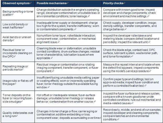
Important diagnostic principle: determine at which stage the defect is created. If the toner image is already defective before fusing, focus first on charging, development, transfer, and cleaning. If the unfused image is satisfactory but the finished page has poor adhesion or fuser-related contamination, investigate fusing and media conditions. Use the machine’s service procedures and suitable test methods rather than relying on appearance alone.
6. A Practical Validation Plan for Compatible Consumables
6.1 Define the exact target configuration
Record the target machine model, consumable part numbers, development architecture, photoconductor and cleaning design, fuser type, supported paper range, normal operating settings, and expected duty cycle. A broad brand-level compatibility statement is not a substitute for model-specific validation.
6.2 Characterize the materials and components
Depending on the product and available laboratory capability, useful checks may include toner particle-size distribution and morphology, charge polarity and Q/M distribution, flow behavior, thermal and rheological properties, and performance under relevant environmental conditions. For drum and fuser assemblies, check material and batch traceability, surface condition, dimensions, electrical characteristics where applicable, mechanical contact, heating response, and other model-specific parameters.
6.3 Test the full imaging cycle
Use the intended toner with the target drum/developer configuration. Include text, fine lines, solid fills, multiple halftone levels, and non-image areas. Record density and uniformity, background, edge quality, transfer performance, residual toner, and any visible contamination. In two-component systems, include the specified carrier and normal toner-replenishment process where applicable.
6.4 Validate fusing separately and in the full system
Assess fixation and release under the target machine’s normal operating settings and supported media conditions. A controlled test plan can include adhesion or rub testing, image gloss and uniformity, high-coverage images, repeated output, and inspection of fuser surfaces after a defined print run. A single hand-rub test or one short print sample is not enough to establish long-term compatibility.
6.5 Run a controlled durability test
Capture samples at the beginning, intermediate stages, and the defined end point of the test. Where relevant, assess continuous printing, different coverage levels, approved media types, and environmental conditions representative of the intended market. Define page counts, sampling intervals, acceptance limits, and stop criteria based on the engine, rated life, product risk, and customer requirements—not as a universal page-count rule for every model.
6.6 Change one variable at a time
When a defect appears, use a known-good reference component or consumable and change one variable at a time where practical. Record the exact configuration, batch numbers, machine settings, paper type, print count, environmental conditions, and result. This makes it easier to distinguish a toner-formulation issue from a worn fuser, contaminated developer, damaged OPC, incorrect setting, or batch variation.
6.7 Model-Specific Testing: Ricoh MP 3554 and IM 3000 Platforms
The Ricoh MP 3554 and IM 3000 platforms are practical examples of why toner, drum-unit, and fuser compatibility must be evaluated as a complete system. Hotsun’s model-specific testing work covers the compatible drum unit, toner, and fuser assembly together, with particular attention to the demanding toner requirements of these engines. Charging behavior, development stability, transfer performance, residual-toner cleaning, melt rheology, and release behavior all need to remain compatible with the target machine’s operating conditions.
A successful short print test alone cannot establish long-term compatibility. Evaluation should consider the intended component combination and operating conditions, and should document image quality and any changes observed over a defined print run. Test parameters and acceptance criteria must be interpreted in the context of the specific machine and configuration rather than treated as universal values.
For industry professionals interested in this Ricoh platform testing, detailed technical parameters, evaluation methods, and test reports are available upon request. Please contact Hotsun to discuss the relevant test data and compatibility requirements for your application.
7. What This Means for Compatible Consumables Manufacturers
Reliable compatible consumables depend on quality control at three levels:
• Material-level control: maintain traceable material and batch information and use test methods tied to relevant performance characteristics.
• Component-level control: validate drum/developer units for charging, development, transfer, cleaning, and image stability; validate fuser assemblies for thermal response, nip behavior, fixation, release, and durability.
• System-level control: test the actual toner, drum/developer configuration, and fuser combination intended for sale in the target machine.
This layered approach helps explain why two consumables that look similar or perform well in a short demonstration may behave differently in extended use. The objective is not merely to reproduce initial print quality; it is to maintain consistent performance while avoiding preventable contamination, excessive cleaning load, poor fixation, and premature component wear.
Conclusion: True Compatibility Is Measured in the Complete Machine
Modern toner is an engineered material whose electrostatic, surface, flow, and thermal properties must work within the limits of the target print engine. The drum or photoconductor system must form and transfer the image while reliably managing residual toner. The fuser must convert the loose toner image into a durable print while releasing it cleanly from its working surface.
No single specification—particle shape, average Q/M, softening temperature, physical fit, or initial print appearance—can prove compatibility on its own. The strongest evidence comes from controlled, repeatable testing of the actual consumable combination in the intended machine, with clearly defined acceptance criteria and documented results over a representative operating cycle.
True compatibility is not simply about making an individual part resemble the original. It is about ensuring that the toner, imaging components, fuser, paper, and machine operate together consistently and reliably.
Technical References
1. Imaging Society of Japan / Society for Imaging Science and Technology, “Electrophotography Overview,” covering toner, development, transfer, fusing, and cleaning. Read the overview.
2. Y. Matsumura et al., “Technology Development of Emulsion Aggregation Toner for High Quality Color Printing and Lower Environmental Impact,” Journal of Imaging Science and Technology, 2003. View publication.
3. H. Kambara et al., “External Additives for Toners: Characteristics of Fumed Silica, Colloidal Silica, and Next Generation Materials,” IS&T NIP28, 2012. View publication.
4. L. B. Schein, “Recent Advances in Our Understanding of Toner Charging,” Journal of Electrostatics, 46(1), 1999, pp. 29–36. View publication.
5. K. Seino, S. Yuge, and M. Uemura, “Wear Characteristics and Cleaning Ability of Cleaning Blades,” Journal of Imaging Science and Technology, 47(5), 2003, pp. 424–433. View publication.
6. N. Kim et al., “Fusing Quality of Toner with Tunable Thermal Properties,” IS&T NIP29, 2013, pp. 438–443. View publication.
7. S. S. Hwang, “Toner Penetration into Paper at Fusing,” Journal of Imaging Science and Technology, 44(1), 2000, pp. 26–30. View publication.
8. Xerox, “The Story of Xerography,” company history resource. Read the history PDF.