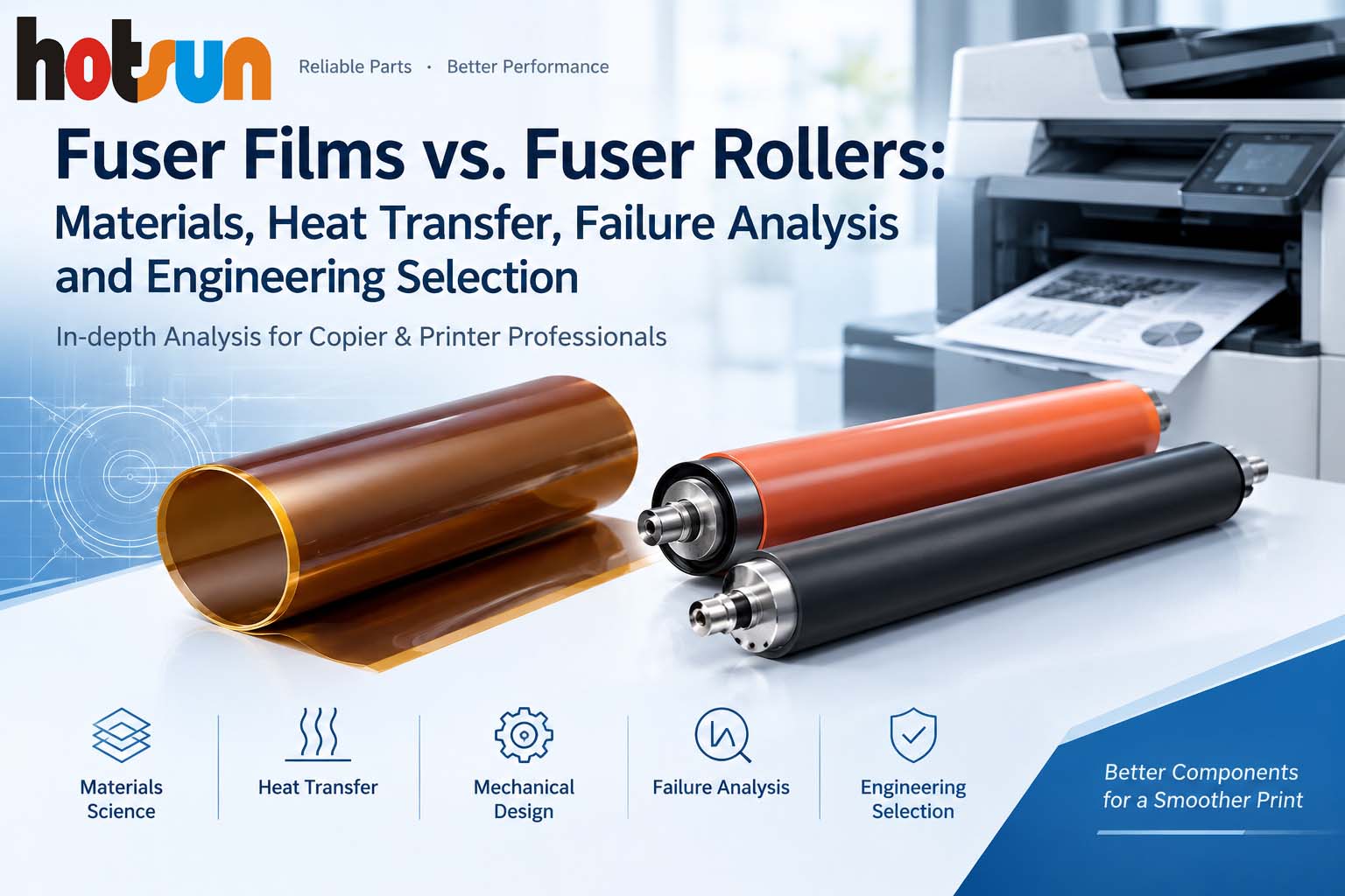
1. The Core of Fusing: Heat, Pressure and Release
During electrophotographic printing, toner is developed and transferred onto paper. At this stage, the image may not yet have sufficient resistance to rubbing, bending or long-term handling. The fuser applies heat and mechanical pressure to soften and flow the thermoplastic resin in the toner, helping it bond firmly to the paper surface. At the same time, the fusing surface must provide suitable release properties to reduce toner adhesion and offset.
Fusing performance depends on several interacting factors:
- **Heat transfer:** whether sufficient energy reaches the toner and paper within the available contact time.
- **Contact mechanics:** whether nip width, pressure and axial pressure distribution meet the design requirements.
- **Toner rheology:** whether the toner resin softens adequately under the actual temperature and dwell time.
- **Surface chemistry and tribology:** whether toner releases consistently and the film or roller withstands heat, pressure and friction over time.
A fuser film and a fuser roller are not universal alternatives that can be compared independently of the machine. They represent different fusing architectures, and their design can affect warm-up, temperature recovery during continuous printing, image gloss, paper separation and maintenance requirements. Actual performance also depends on the heating method, control strategy, toner, paper and overall machine design.
High-quality, reliable fixing performance depends on a perfect balance among the key engineering parameters mentioned above.
2. Fuser Films and Fuser Rollers: Structure and Operating Principles
2.1 Film-Based Fusing Systems
A typical film-based fusing system includes a fuser film, a heater (often a ceramic heater), a pressure roller, film guides or support structures, temperature sensors, over-temperature protection and a lubricant compatible with the specific design.
The film commonly uses a heat-resistant polymer substrate such as polyimide (PI), and its outer surface may include a release layer. During operation, the film moves around its support structure. Its inner surface slides against the heater, while the pressure roller drives or cooperates with the film. Paper passes through the nip to complete the fusing process.
One common design advantage is the film’s relatively low thermal mass, which can enable a fast thermal response when paired with a suitable heater and control system. However, low thermal mass can also make temperature more sensitive to paper heat load, print speed, heater power and control strategy.
Reliable operation depends on dimensional accuracy, guide geometry, inner-surface friction, lubricant distribution, heater-surface condition and drive-system compatibility. Film thickness or material name alone cannot establish product quality.
2.2 Roller-Based and Hybrid Fusing Systems
A conventional roller-based fuser generally includes a heated roller and a pressure roller. The heated roller may combine a metal core, an elastic layer and an outer release layer, with heat supplied by a halogen lamp, induction heating or another design. The exact construction varies by model; not all heated rollers have the same layer structure.
A pressure roller typically consists of a core and an elastic layer, and some designs also use a surface coating. The elastic layer deforms under load to form the fusing nip. A roller system’s thermal storage depends on roller mass, material properties and the heating method. The terms “roller fuser” alone do not prove that warm-up will be slower or continuous-print performance will be better.
Important control factors include roller diameter, roundness, radial runout, elastic-layer thickness and hardness, modulus at operating temperature, compression set, coating adhesion and nip-pressure distribution.
Some machines use fusing belts, external heating rollers or other hybrid architectures. For service and purchasing decisions, consult the service manual and parts catalogue for the exact model rather than inferring internal construction from the labels “film-based” or “roller-based.”
3. Materials Science: System Compatibility Matters More Than One Parameter
3.1 Fuser Film Substrates
Polyimide (PI) is used in many film-based fusing systems because of its heat resistance, dimensional stability and flexibility. Performance can vary significantly with PI formulation, film-forming process and composite construction. A single glass-transition temperature, coefficient of thermal expansion or dimensional tolerance should therefore not be treated as a universal specification for all fuser films.
For development and incoming inspection, assess the following against the specific machine and original design:
1. Film thickness and its circumferential and axial uniformity.
2. Loop circumference, inner diameter, roundness and axial dimensions.
3. Dimensional change after thermal cycling.
4. Tear resistance and repeated-bending fatigue.
5. Compatibility between the inner surface and the specified lubricant.
6. Adhesion stability between the outer coating and substrate.
7. Tracking, drive resistance and durability in the actual machine.
Excessive thickness may increase thermal resistance and bending stiffness; insufficient thickness may reduce mechanical strength or make defects more consequential. Acceptable limits must be established for the specific design and verified by testing. A single thickness or tolerance should not be applied indiscriminately to all Canon, Ricoh, Konica Minolta or Xerox models.
Metal-substrate and composite fusing belts or films are also available in the market. Material type, thickness, thermal conductivity, tear resistance and model compatibility should be supported by traceable material data, physical analysis and machine testing—not inferred from a product name or one isolated material value.
3.2 PFA, PTFE and Release-Layer Design
PFA and PTFE are fluoropolymers known for heat resistance and low surface energy, but their processing methods, mechanical properties and application conditions differ. Depending on the component, a fuser may use different fluoropolymers, primer systems or multilayer coatings.
It is not accurate to state categorically that PFA is always more wear-resistant than PTFE, or that PTFE coatings inevitably crack. Coating performance depends on formulation, thickness, substrate preparation, coating and curing processes, thermal cycling, mechanical deformation and the operating environment.
Useful evaluation items for compatible fuser films and rollers include:
Test Engineering Purpose
Coating thickness and uniformity Assess local thermal resistance and wear risk
Coating adhesion Evaluate bonding stability between coating and substrate
Surface condition after thermal cycling Identify cracking, blistering or delamination
Release performance after continuous printing Assess toner offset and surface-contamination risks
Inner-surface wear Check compatibility between lubrication and the heater-contact interface
Coating thickness measurements or visual inspection alone cannot establish long-term reliability.
3.3 Pressure-Roller Elastic Layers
Pressure-roller elastic layers may use solid silicone rubber, foamed silicone rubber or other materials validated for the intended design. These structures differ in density, compression response, heat transfer and recovery. No one material type is automatically superior for every machine.
Pressure-roller performance should be evaluated using several parameters:
• Shore hardness and the conditions under which it is measured.
• Elastic modulus at operating temperature.
• Elastic-layer thickness, uniformity and structure.
• Compression set.
• Changes in hardness and recovery after thermal ageing.
• Thermal conductivity and thermal stability.
• Adhesion between the surface coating and elastic layer.
• Nip geometry under actual operating temperature and load.
Two rollers with the same hardness can still produce different nip widths and pressure distributions because of differences in layer thickness, modulus, cell structure or compression set. Hardness is important, but it is not a sufficient measure of fusing performance.
ASTM D395 is a test-method standard for compression set of rubber. Test conditions, specimen configuration and acceptance criteria should be selected according to the applicable standard and product specification. A single compression-set percentage should not be presented as a universal pass/fail limit for every fuser pressure roller.
3.4 Release-Layer Failure
A fuser roller’s surface coating must balance toner release, heat resistance, wear resistance and adhesion to the underlying layer. Failure may involve microcracks within the coating or at an interface, thermal-expansion mismatch, mechanical stress, material ageing or process defects.
Combine room-temperature inspection with thermal cycling, mechanical loading, continuous-printing tests and actual toner-contact testing. Coating delamination should not automatically be attributed to silicone-oil migration, and a surface scratch test alone cannot predict service life.
4. Thermal Performance: Why Can Fusing Be Poor Even When the Temperature Looks Normal?
Reaching a controller’s target temperature does not necessarily mean that the toner receives enough heat during its brief passage through the nip. Paper weight and moisture, toner coverage, print speed, nip width and material properties all affect the result.
Important variables include:
• Fusing-surface temperature and temperature uniformity.
• Paper temperature and moisture before entering the fuser.
• Softening and melting behaviour of the toner resin.
• Thermal properties of the film, rollers, elastic layers and paper.
• Nip width, pressure distribution and paper speed.
• Heater power and temperature recovery during continuous printing.
4.1 Estimating Fusing Dwell Time
If the effective nip width is \(w_n\) and paper speed through the nip is \(v\), a first-order estimate of dwell time is:
\[
t_n \approx \frac{w_n}{v}
\]
For example, if the assumed nip width is 8 mm and paper speed is 300 mm/s:
\[
t_n \approx \frac{8}{300}=0.0267\ \text{s}
\]
This is approximately 26.7 ms. The values of 8 mm and 300 mm/s are illustrative assumptions, not measured specifications for a particular machine.
The calculation shows that fusing takes place within a short time window. Even at the same target temperature, different nip widths, thermal resistances and paper speeds can produce different results.
4.2 Thermal Resistance in Multilayer Structures
For a simplified one-dimensional steady-state model, the total thermal resistance of multiple layers can be expressed as:
\[
R_{\mathrm{th}}=\sum_i\frac{L_i}{k_i A}
\]
Here, \(L_i\) is the thickness of layer \(i\), \(k_i\) is its thermal conductivity and \(A\) is the effective heat-transfer area. The heat-transfer rate can be approximated as:
\[
\dot Q\approx\frac{\Delta T}{R_{\mathrm{th}}}
\]
These relationships show how layer thickness, thermal conductivity and interface resistance influence heat transfer. Actual fusing is transient and is also affected by thermal mass, contact resistance, pressure changes, and the thermal properties of paper and toner. The equations explain the underlying principles; they cannot independently predict the performance of a complete printer.
4.3 Device Warm-Up Time Is Not the Same as Fuser Performance
Device warm-up time, fusing-surface temperature recovery and fusing performance during continuous printing are different metrics.
For example, Ricoh’s published specifications list an A4 continuous output speed of 25 pages per minute and a 21-second warm-up time for the IM C2500. These are device-level specifications. They do not independently demonstrate the thermal response or durability of a particular fuser film, pressure roller or compatible fuser unit.
When comparing fuser components, control for the machine model, environment, paper, toner coverage and test method.
5. Model Examples: How to Use Parts Catalogues Correctly
Part numbers help identify a component and its stated application, but they do not by themselves establish material formulation, operating temperature, nip width, coating thickness or actual service life. The following examples illustrate the information that should be verified during service and purchasing.
5.1 Canon imageRUNNER ADVANCE C256i
A publicly available parts catalogue lists the following references:
• Fixing Film Assembly: FM1-R730-000
• Pressure Roller Kit: FM1-K198-010
Reference: https://printcopy.info/?brand=Canon&mod=pc&model=iR+Advance+C256i&page=37
These numbers can be used as leads for further verification. Before ordering or servicing, confirm the complete model suffix, regional version, supersession history and actual applicability. Different C256i variants may differ; the family name alone does not prove that every component is interchangeable.
For this type of film-based assembly, inspect the fit between the film, heater and support structure; inner-surface lubrication; pressure-roller surface and nip condition; installation of temperature sensors and over-temperature protection; and film wear and release performance after extended operation.
5.2 Ricoh IM C2000–IM C6000 Series
Third-party service material lists the following component references for certain models:
• Fixing Film
• Lower Pressure Roller
• Oil Application Pad
During service, assess the film, pressure roller and lubricant-supply components as an interacting system. Verify lubrication delivery, contact interfaces and paper-separation performance.
5.3 Konica Minolta AccurioPress C3080/C3070 Series
Publicly available third-party service and parts information lists the following references:
• Fusing Belt Assembly: A9VER70400
• Fusing Roller/Lw: A50U765500
• Fusing Heater Lamp/Up: A9VEM31F00
Reference: https://www.anyservicemanuals.com/downloads/konica-minolta-accuriopress-c3080-c3080p-c3070-accurioprint-c3070l-sm/
This example illustrates why some production systems cannot be classified simply as film-based or conventional roller-based designs. Certain machines use a combined arrangement of a fusing belt, rollers, heating components and related mechanisms.
Evaluation should cover belt tracking, belt-to-roller contact, heater and sensor operation, component wear, and temperature distribution and image-gloss consistency during extended printing. Material type and thickness should be confirmed using reliable technical documentation or physical analysis.
5.4 Xerox AltaLink C8130/C8135/C8145/C8155/C8170 Series
A third-party parts catalogue lists the following fuser references:
• 607K22310: C8130/C8135
• 607K22320: C8145/C8155
• 607K22330: C8170
Reference: https://www.iteminc.info/dlcuploads/Xerox-AltaLink-B8145–B8155–B8170–C8130–and-Options-Parts-Catalog-66c63d6e2ca50.pdf
These references illustrate the distinctions shown in the cited catalogue. Before ordering, verify the complete model, regional voltage version and latest parts-supersession information. Similar appearance or mounting position does not establish that heating structures, electrical specifications or assemblies are interchangeable.
6. Failure Analysis: Build a Verifiable Diagnostic Path from Print Defects
Fuser troubleshooting should not rely on replacing a component based on a single symptom. A more reliable approach links the observed condition to possible physical mechanisms and verification steps.
6.1 Fuser Film Wrinkling, Folding or Edge Damage
Possible causes include incorrect film dimensions or roundness, worn guides, assembly misalignment, insufficient or uneven lubrication, heater-surface damage, or mechanical interference between the film and support structure.
Inspect film tracking, guides on both sides, inner-surface wear, lubricant distribution and the heater-contact surface. A folded film does not, by itself, prove that the film is too thin.
6.2 Inner-Surface Wear or Scratching
Abnormal friction at the film–heater interface can cause wear marks, scratches or local damage. Check:
. Whether the lubricant meets the requirements for the specific model.
. Whether the lubricant has dried out, migrated or become contaminated.
. Whether the heater surface has burrs, debris or local damage.
. Whether particles are embedded in the film’s inner surface.
. Whether film drive resistance has changed abnormally.
Dark deposits should not be identified as carbonized grease based on appearance alone. Their location, material condition and operating history should also be considered.
6.3 Fuser Roller Coating Peeling
Coating failure may be associated with substrate preparation, primer systems, thermal-cycle stress, mechanical fatigue, material ageing or chemical incompatibility. Determine whether the failure occurred within the coating or at an interface, compare new and failed parts, and use appropriate adhesion, thermal-cycling and mechanical-load tests.
The page count at failure alone cannot establish a specific service life or prove a process defect. Record the machine model, paper, operating conditions, sample count and failure mode.
6.4 Pressure-Roller Flat Spots
A pressure roller held under heat and load for an extended period may develop permanent deformation or compression set, changing the nip geometry. Check roller roundness, radial runout, elastic-layer hardness and recovery, and compare defects at cold start with those after continuous operation.
If a defect is more pronounced at start-up and becomes less obvious after running, local roller deformation may warrant investigation. Other mechanical and temperature-control causes must still be ruled out.
6.5 Toner Offset and Poor Fusing
Poor fusing does not necessarily mean that the temperature is too low; toner offset does not necessarily mean that the release coating is defective. Check, in order:
. Whether the paper type matches the machine settings.
. Whether temperature control, sensors and the heating system operate correctly.
. Whether temperature recovery is insufficient during continuous printing.
. Whether the toner is compatible with the machine and fusing conditions.
. Whether the fusing surface is worn, contaminated or locally adhesive.
. Whether nip width and pressure distribution meet the design requirements.
For repeating image defects, compare the repeat interval with the theoretical circumference of candidate rotating components:
\[
C=\pi D
\]
Here, \(C\) is the theoretical circumference and \(D\) is the effective diameter. This can support preliminary diagnosis, but actual intervals may be affected by slip, elastic deformation, gear ratios and measurement error. A similar circumference alone does not confirm the faulty component.
6.6 Lubrication and Maintenance
Fuser-film lubricant must be compatible with the specific heater, film inner surface and operating temperature. Different machines may specify different lubricant types or materials, so one lubricant, brand or fixed quantity should not be treated as a universal solution.
Follow the service manual for lubricant type, application location and quantity. Insufficient, excessive or uneven lubrication—or material incompatibility—can affect film movement, friction, contamination and durability. If the service documentation does not specify a quantity, do not generalize a value from another model.
7. Selection Guidance for Purchasing, R&D and Service Teams
Step 1: Confirm the model and assembly version. Check the full model designation, regional voltage version, part number and supersession information.
Step 2: Confirm the material structure. For films, inspect the substrate, coating and lubrication system. For rollers, inspect the core, elastic layer, surface coating and geometric accuracy.
Step 3: Verify assembly compatibility. Check the fit among guides, pressure rollers, gears, bearings, heaters and temperature sensors.
Step 4: Test in the actual machine. Evaluate warm-up, continuous printing, fusing across the intended paper range, image gloss, toner offset and mechanical operation.
Step 5: Validate durability. Record changes at defined intervals instead of judging quality from the first prints after installation.
For professional buyers, a reliable compatible-parts supplier should be able to provide verifiable material specifications, dimensional controls, test conditions, batch traceability and clear model-compatibility information.
8. Technology Directions: From Individual Material Metrics to System-Level Matching
Fuser development is not only about improving a single material; it also requires balancing thermal, mechanical, frictional and surface-release performance.
For fuser films, development priorities include substrate dimensional stability, film durability, coating adhesion, low-friction interfaces and long-term lubricant stability. For fuser rollers, priorities include the thermomechanical stability of the elastic layer, compression-set control, coating durability and uniform nip pressure.
Low-thermal-mass designs, metal substrates, composite release layers and self-lubricating surfaces should be evaluated against the intended design. Any claimed improvement in warm-up, energy use or durability must be verified through material characterization, machine testing and long-term operating data. Likewise, low-temperature fusing toner may change system heat load, but the actual benefit depends on toner formulation, paper, machine control and image-quality requirements. A universal energy-saving percentage or temperature range should not be assumed.
For compatible-parts developers, long-term competitiveness comes from linking material selection, dimensional control, assembly accuracy and real-machine testing in a repeatable feedback loop—not simply maximizing hardness, increasing coating thickness or minimizing material cost.
9. Conclusion: Fusing Performance Depends on the Balance of the Entire Interface
The difference between a fuser film and a fuser roller is not merely the difference between a flexible film and a cylindrical roller. They represent different approaches to heat transfer, mechanical contact and surface release.
For fuser films, key factors include dimensional accuracy, inner-surface friction, lubrication stability, release-layer durability and drive compatibility. For fuser rollers, key factors include the thermomechanical properties of the elastic layer, nip geometry, roller accuracy and coating stability.
Both must provide appropriate heat, pressure and consistent release under the intended machine, toner, paper and operating conditions. Understanding these interactions helps service engineers distinguish heat-transfer problems from nip irregularities, lubrication failures and surface-release issues.
For compatible-parts manufacturers, competitiveness is not achieved simply by making a new component look like an OEM part. It comes from material control, dimensional accuracy, batch traceability and systematic durability testing that support repeatable performance in real applications.
A reliable fuser is not the component with the highest single material specification. It is the component that balances heat transfer, mechanical pressure, friction and surface release for the intended machine, toner, paper and operating conditions.
About HOTSUN
Zhongshan Hotsun Imaging Products Co., Ltd. specializes in the development, manufacture and supply of compatible and remanufactured imaging components and consumables for office printing equipment. We emphasize material selection, manufacturing process control and real-machine testing, serving copier-consumables distributors, service providers and professional partners worldwide.
Website: https://www.hotsunimaging.com/
Technical and product enquiries: [email protected]
Technical note: Model and part-number references in this article are compiled from publicly available parts catalogues or supplier service materials. Device warm-up times and print speeds are based on published manufacturer specifications. Third-party part numbers are not OEM part numbers. Material properties, operating temperatures, lubricant requirements, compatibility and service life must be confirmed using the relevant model documentation and validated test data.